Understanding Complex Signals
Complex isn't always complicated
While learning about digital signal processing (DSP), one thing that's been confusing me is talk about complex signals. Complex signals are complex in the mathematical sense, so they're composed of a real and imaginary part. Let's talk about what that means.
Imagine a simple signal represented by a sinusoidal wave and transmitted over radio frequency (RF). We need to effectively model this signal as we receive it over the air. Our receiving circuit can find the amplitude and phase angle of the signal. With that, we can plot these two parameters on a complex plane as polar coordinates. This model is called a phasor.
With these two parameters, we can model the incoming signal using Euler's formula, . That's some tricky math, and it came quickly, so let's take some time to understand what it means and why we need it.
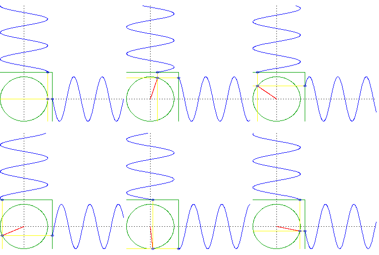
Remember that our incoming signal is a simple sinusoid. Let's look at how that signal affects our phasor.
Notice that, as the signal reaches our antenna, our phasor's phase angle changes according to the signal's phase. Ultimately, our circuit will be processing what the phasor does, so let's look at the signal that the phasor itself produces for our circuit.
Looks the same as the RF signal, right? For the most part, it is. The resulting signal is in-phase with the RF signal, which means that they're essentially synchronized. This is how the vast majority of analog radio receivers work, and the signal received over the air can be used for later signal processing. For DSP, however, we can't make many assumptions about how the computer will be processing the data, and some processing systems may find it difficult just to process the one original signal.
Luckily, it's pretty easy for us to create two useful signals from the one original. With these two, we can make tasks that are usually complicated with one signal much simpler for the computer: tasks like demodulation.
Put simply, our phasor gives us two signals: the in-phase signal that we saw previously and the quadrature signal that's produced at a 90° offset from the in-phase signal. Because this offset in phase is a quarter-rotation off of the in-phase signal, it's called the quadrature signal.

The quadrature signal has an interesting property here in that it's imaginary. Recall that we're on a complex plane, so the vertical axis consists of imaginary numbers. Because the quadrature signal oscillates on this axis, the signal is also imaginary.
Making sense of the math
We can model the simple sinusoid of our RF signal mathematically using the cosine function, . And, because the in-phase signal is essentially identical, we can also use cosine to model it, as well.
How do we model the quadrature signal, then? Well, the quadrature signal is out of phase with the in-phase signal by 90°, which means it can be modeled by , which is equal to .
With being our in-phase signal and being our quadrature signal, we can mathematically represent both signals together using Euler's formula.
Here, we're saying that the two parameters we receive from the RF signal, and , can be equally represented using two signals: one that's in-phase with the RF signal and one that a quarter-rotation out of phase with it. The RF side of the equation is the left-hand side, , and the side that's processed by the computer is the right-hand side, . Of course, our equation shows us that both sides are equivalent, so the information we're processing is the same as the information we received over the air.
In reality, the signal that we're receiving over the air isn't a basic sinusoid, but this exercise helps us build some intuition about the use of complex signals in DSP.
In Practice, the I and Q
In practical DSP, you may not always hear about processing a real and imaginary signal, but the odds are that you've heard of them or have been using them without knowing! Many DSP applications require processing of I/Q data. I/Q data is the data that we use to process signals received over the air, and we get them by sampling the complex signals we've been talking about. Specifically, I refers to the in-phase signal, and the Q refers to the quadrature signal.
Why is this called "complex"?
This is because the right-hand side of our equation is one part real and one part imaginary, and it follows the form of all two-dimensional complex values: .
Why do this?
As stated before, converting the RF signal into two signals to be processed like this makes tasks like demodulation much simpler and more robust.
How does this make demodulation easier?
I cover this briefly in the next post.
To wrap up
I hope this made the concept of complex signals easier for you to understand. If you have any questions or would like to offer ways that I can improve this post, feel free to contact me.